


Every amplifier sends its hardest job down two pieces of copper. Unlike the line-level signals that travel between a mixer and a processor, a speaker feed carries real current, and any resistance in the run sits directly in series with the driver. Gauge and length are the two variables that decide how much of that resistance you accept — and once you can read a spec sheet, the arithmetic becomes surprisingly simple. This guide walks through what gauge and length actually change on stage and in fixed installs, using the figures printed on our own FC series speaker cable data table.
LESOUND builds speaker cable in both bare-wire and terminated form — the FC series of flexible OFC cable plus the SC range of finished assemblies — alongside the wider cable programme you can browse on our cables overview page. The same physics applies to both.
What a Long Speaker Run Actually Does
Put simply, cable resistance steals two things: power and control.
Power. The cable and the driver form a voltage divider. Whatever resistance the cable adds, a share of the amplifier’s voltage drops across the copper instead of the voice coil. Double the length and you double the round-trip resistance; halve the cross-section and you roughly double the resistance per metre. Neither effect is mysterious — both are printed on the data table.
Control. A loudspeaker is an electromechanical system: as the cone moves, the voice coil acts as a generator, and the amplifier damps that motion through the same pair of conductors. Extra series resistance weakens that damping, most audibly around bass resonance. This is why long thin runs are a worse idea on a subwoofer feed than on a mid-high feed carrying far less current.
Neither of these effects shows up as distortion figures or noise — the signal arriving at the driver is a faithful copy of what left the amplifier, just slightly smaller and slightly less well controlled. That is what makes gauge and length worth planning: the loss is quiet, cumulative, and entirely predictable.
Reading Gauge on a Spec Sheet: mm² and AWG
Speaker cable is specified by conductor cross-section, in square millimetres (mm²) in most of the world, or AWG in North America. Bigger number in mm² means thicker copper; bigger number in AWG means thinner copper. The two scales run in opposite directions, which is the single most common source of ordering mistakes.
Our FC series data table pairs every gauge with a maximum resistance figure per kilometre. The table below condenses the two-core range:
| Model | Conductor | AWG | Jacket OD | Max resistance (Ω/km) |
|---|---|---|---|---|
| FC240 | 2 × 4.0 mm² | 11 | Ø9.6 mm | ≤ 5 |
| FC233 | 2 × 3.3 mm² | 12 | Ø9.0 mm | ≤ 6 |
| FC225 | 2 × 2.5 mm² | 13 | Ø8.3 mm | ≤ 8 |
| FC220 | 2 × 2.07 mm² | 14 | Ø8.0 mm | ≤ 10 |
| FC215 | 2 × 1.5 mm² | 15 | Ø7.2 mm | ≤ 14 |
| FC213 | 2 × 1.31 mm² | 16 | Ø7.0 mm | ≤ 16 |
| FC210 | 2 × 1.0 mm² | 17 | Ø6.5 mm | ≤ 21 |
| FC208 | 2 × 0.83 mm² | 18 | Ø6.0 mm | ≤ 25 |
The conductors are drawn from 99.9% OFC copper, and the jacket is a super-flexible PVC compound designed to coil and uncoil cleanly at cold outdoor temperatures. Two adjacent gauges differ by roughly 25–30% in resistance, so stepping one size up the table makes a measurable — though not always audible — difference on long runs, and almost none on short ones.

The Arithmetic, in Plain Numbers
Resistance figures are quoted per kilometre, but the current makes a round trip — out through one conductor and back through the other — so every metre of cable puts roughly two metres of copper in the loop.
Take 2.5 mm² at 8 Ω/km: that is 0.008 Ω per metre. A 15-metre run therefore adds 15 × 2 × 0.008 = 0.24 Ω in series with the driver. Against a 4 Ω cabinet that is 6% of the load impedance; against an 8 Ω cabinet it is 3%. The power that ends up in the cable instead of the driver is of the same order — small on a 10-metre jump, significant on a 50-metre one at 18 AWG.
Run the same length on FC240 at 5 Ω/km and the loop resistance drops to 0.15 Ω. This is the entire decision in miniature: length you cannot change, gauge you can.
A Practical Rule of Thumb
Keep the round-trip cable resistance comfortably below roughly 5% of the driver’s nominal impedance, and you keep both the wasted power and the damping change in a range that engineering practice treats as negligible. Below 10 metres, any of the mid-table gauges meets that bar for an 8 Ω load; beyond 20 metres, or on 4 Ω subwoofer feeds, the thicker end of the table earns its jacket diameter.
Length: Plan the Run Before You Order the Reel
Length is the variable buyers underestimate. A stage plan drawn on paper usually forgets the vertical drop from a flown cabinet, the detour around a drum riser, and the spare coil every technician tucks behind a wedge. A 20-metre need on the drawing becomes 30 metres on the floor.
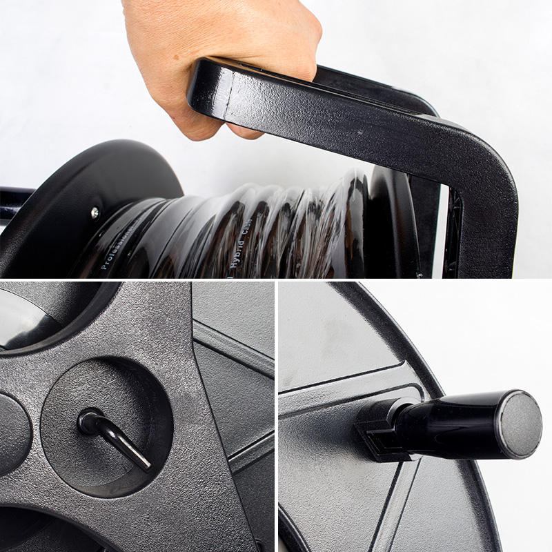
The FC series is supplied in 1, 2, 3, 5, 10, 15, 20, 30, 50 and 100-metre lengths, on spools or reel drums for the longer options. The finished SC range follows the same logic in terminated form. Ordering the next size up is inexpensive insurance against floor reality; ordering cable that is too short, on the other hand, invites the worst workaround in live sound — joining two runs with a makeshift connector pair, which adds contact resistance and a failure point precisely where nobody can watch it.
Multi-Core Options for Complex Rigs
Where several feeds travel the same route — bi-amped cabinets, or a cluster fed from one rack — the FC range extends beyond the two-core format: four-core (FC410–FC440), six-core (FC610–FC640) and an eight-core FC825 share the same conductor sizes and resistance figures as the two-core table above. Pulling one multi-core jacket along a truss or through a duct replaces several separate runs and makes the total resistance per circuit identical to its two-core equivalent.
Termination: Where Good Copper Goes to Die
Resistance arithmetic assumes clean metal-to-metal contact, and that assumption fails most often at the ends. A screw-terminal connector with an under-tightened strand, or a solder joint wetted onto insulation rather than copper, can add more series resistance than thirty extra metres of correct cable. Two details matter:
- Conductor preparation. The fine OFC strands in flexible speaker cable must be twisted, fully captured, and protected from work-hardening at the entry point. The FC jacket is dimensioned so the conductor lands cleanly on binding posts or inside speakon-type contacts without stray strands.
- Finished assemblies. Where the run is standard, the SC range of terminated speaker cables — including 13 AWG and 15 AWG builds — removes the human variable entirely by arriving with factory-crimped, factory-tested ends.

From Amp Rack to Speaker: Where This Sits in the Chain
Speaker cable is the last link of the signal chain, and it behaves differently from everything before it. Line-level feeds — the microphone cables and snake cables between stage and rack — carry millivolts, where shield design and interference matter more than gauge. Once the signal has been amplified, interference stops being the enemy and resistance takes over. That is why the two cable families are specified in different currencies: shielding and capacitance for line level, cross-section and resistance for speaker level. If you are mapping a full rig, our audio cables page groups both families.
The same planning applies to portable rigs. A typical DJ booth or DJ table puts the amplifiers — or the powered tops — within a few metres of the drivers, which is why 13–15 AWG workhorse cable covers most mobile jobs; a conference hall or a distributed install immediately pushes you up the table.
A Pre-Order Checklist
- Total run length, both ways. Measure the route, not the map — vertical drops, floor detours and service loops included — then add one length step.
- Load impedance. 4 Ω feeds forgive half the resistance that 8 Ω feeds do. Subwoofer runs deserve the thicker end of the table.
- Gauge in mm² and AWG. Convert carefully; the scales run opposite directions. Our data table lists both.
- Round-trip resistance. metres × 2 × Ω-per-metre, held below ~5% of load impedance.
- Core count. Bi-amp and cluster feeds may suit a four- or six-core jacket rather than several two-core runs.
- Ends. Bare wire for your own terminations, or factory-terminated assemblies from the SC range where consistency matters more than flexibility.
Closing Note
None of this requires lab equipment — a data table, a tape measure and thirty seconds of arithmetic separate a clean speaker feed from one that quietly trims the low end of a system. The FC series table above is printed on our own specification sheet, and the same figures apply across the two-, four-, six- and eight-core ranges. Buyers comparing suppliers are welcome to put any competitor’s data table beside it: resistance per kilometre, conductor purity and jacket flexibility are exactly the three lines where copper quality shows its hand. Under the LESOUND company and our house brands — Yinyu for stands and cables — the speaker cable programme shares a factory floor with the rest of the ranges on this site, which keeps gauge consistency and termination quality under one roof.
Post time: Oct-15-2026