


Portable PA systems get all the attention, but the installations that hold a venue together are decided at the wall. Every conference room, house of worship, club and school auditorium that runs audio reliably has one thing in common: someone planned the panel sockets and stage boxes before a single cable was pulled. Get that layer right and every future change — a new amplifier rack, a relocated lectern, an added monitor mix — becomes a five-minute patch instead of a half-day of wall chasing.
This guide walks through how we at LESOUND think about fixed-install connectivity, based on the panel-socket, chassis-connector and stage-box families we manufacture for OEM and integration customers. It covers what each component actually does, where it belongs in the signal chain, and the planning details that separate installs that last from installs that get ripped out after two years.
Why Panel Sockets Anchor a Fixed Install
A panel socket is the connector that lives permanently in a wall plate, rack panel, lectern, podium or furniture cutout. Everything else in the room connects to it. That positioning makes it the single most-handled component in the install: stage crews plug into it nightly, cleaning staff dust around it weekly, and visiting engineers judge the whole system by whether it feels solid under their hands.
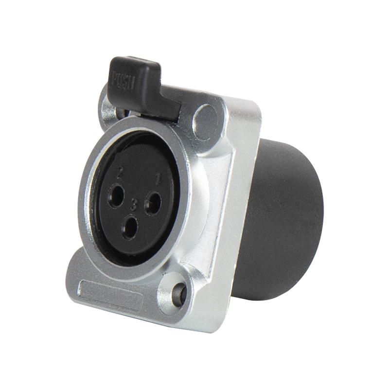
The workhorse of any audio panel is the XLR panel socket. In our SA216 family, these are XLR chassis connectors built for cutout mounting, available in male and female versions so the integrator can decide the direction of signal flow at each wall position. They mate with the microphone cables and audio cables already stocked in the room, so mixing harnesses, spare lines and wall plates all use one connector standard. Alongside them, the XL chassis series (XL009 through XL016) covers the wider spread of panel duties: male and female 3-pin XLR bodies in different flange styles, with solder terminals accessible from the rear of the plate.
Direction of Flow: Male or Female at the Panel?
One of the first decisions on any panel is whether the XLR at the wall is male or female. The convention in most fixed installs is to put the male pin side on outputs and the female socket side on inputs, so that live pins are never exposed on a cable that someone can touch. Microphone inputs from the stage arrive at wall panels as female sockets; feed lines running out to powered speakers or to a remote amp room leave as male. Because both versions exist in the SA216 and XL ranges, the integrator can standardise on one brand of chassis connector across the entire building while still honouring that convention at every plate.
Solder Terminals and Service Access
Panel sockets differ from cable connectors in one important respect: once the plate is screwed to the wall, the rear of the socket is buried in wall space or in a back box. Before committing to a model, check how the solder terminals are oriented and how much clearance the back box provides. A socket whose terminals sit parallel to the plate is easier to work on inside a shallow box than one whose lugs stick straight out the back. This is the kind of detail our OEM customers specify during sampling, because it decides whether a future re-termination takes twenty minutes or an afternoon.
Power at the Panel: Locking Mains Connectors
Audio panels increasingly carry mains power as well as signal, especially in lecterns, DJ booths and presentation walls where a laptop supply, a small mixer or powered speakers all live within arm’s length of the microphone input. A standard household socket has no place on a professional panel: a gentle tug on the cable or a trip over the lead will pull it out mid-event.
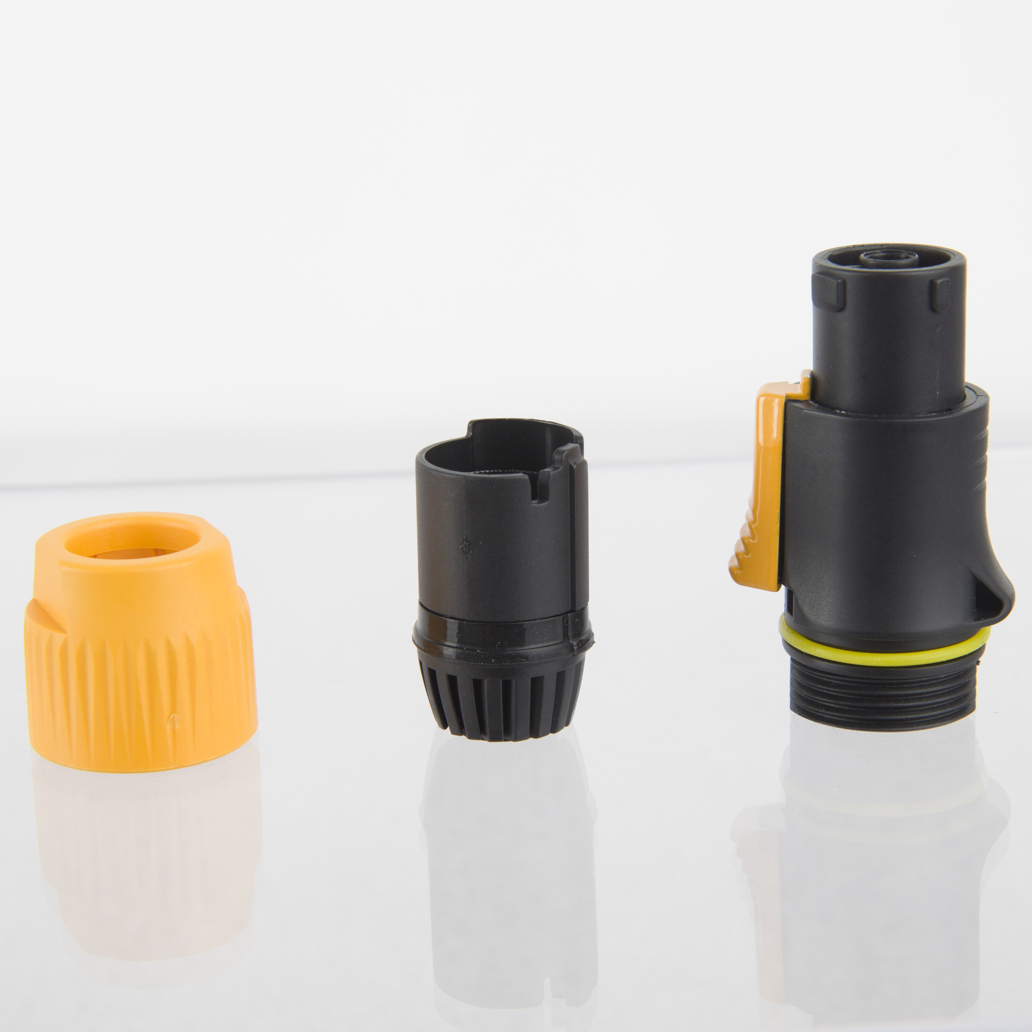
That is where the SA321 family comes in. These are locking mains connectors in the powercon pattern — a round chassis body with a twist-lock ring that latches the mating plug in place. The chassis half mounts in the same cutouts as the audio sockets, so the panel reads as one clean plate rather than a mix of connector types. Colour-coded bodies (the familiar blue and grey pairing used across the industry for power-in and power-through positions) keep crews from cross-patching two different circuits during a changeover.
Keep Power and Signal Separate — Even on the Same Panel
A locking mains connector solves the mechanical problem, but good planning still separates power from signal. Keep mains socket positions at one end of the plate and audio sockets at the other, and route their cables through different knockouts of the back box. Where an audio line must cross a mains run, do it at a right angle. These habits add nothing to the budget at planning time and remove the most common source of hum complaints in finished installs. For a fuller treatment of routing discipline, see our guide on separating power and signal on the same stage.
Stage Boxes: The Other End of the Wall
Panel sockets tidy the room; stage boxes tame the run between the room and the control position. A stage box is a compact hub that converts one long multi-core or digital link into a cluster of standard XLR connections exactly where the musicians and presenters are. Instead of dragging eight individual microphone cables across a hall, the crew lays one snake and patches locally.
Our SNA series handles this job in the most common format of small and mid-sized installs: an aluminium-shell box that turns a single RJ45 line into four XLR positions. The SNA105 presents four female XLRs for microphone inputs, the SNA106 presents four males for returns, and the SNA107 combines both on one chassis for symmetric send-and-return positions. All three share the same housing concept: an extruded aluminium shell that shields the board and survives being stepped on in an equipment case, a snap-on case design that opens without tools for re-patching, and a stackable footprint so four-channel units can be ganged into eight or twelve channels as the room grows. A ground lift switch on the chassis gives the engineer a one-handed fix when a loop between two rooms introduces hum.

For longer multi-core runs, the stage box pairs naturally with the audio snake cables covered in our dedicated guide. The rule of thumb: decide the position of the stage box first, then size the snake, then confirm the RJ45 coupler (our RJ09 and RJA07 barrel couplers) sits where it can be inspected during maintenance rather than buried in a ceiling void.
Planning the Layout: Placement, Numbering and Service Loops
Component selection is half the job. The other half is deciding where each socket goes and how the system is documented. Three habits distinguish professional planning:
1. Place Panels Where Hands Actually Are
Walk the room as the crew will. The lectern panel belongs at the base of the lectern, not on the far wall. The stage panel belongs at the downstage edge near the monitor desk position, and the wireless rack panel belongs beside the antenna distribution. A panel that requires the crew to drag a case across the room will be bypassed — and once a crew bypasses the wall infrastructure, every benefit of the install is lost.
2. Number Everything, on Both Ends
Engrave or heat-shrink label every wall position and every stage-box channel, and use the same numbering in the patch documentation. Our numbering-labelled connector sets exist precisely for this: pre-numbered XLR barrels let a temporary crew re-patch confidently at speed. The two minutes spent labelling during commissioning prevent the guessing games that otherwise surface during a live event.
3. Leave a Service Loop at Every Panel
Terminations fail, and the failure is rarely the connector itself — it is a cable end stressed by a plate that left no slack. Plan a coil of spare cable behind every wall position, long enough that the connector can be pulled out of the back box and reworked on a bench. The same logic applies at the stage box: leave slack before the input so the box can be opened flat without tension on the solder joints.
A Buyer Checklist for Panel Sockets and Stage Boxes
When evaluating suppliers for a fixed-install connectivity programme, the following points cover most of the engineering ground:
- Flange and cutout compatibility. Confirm the chassis cutout dimensions match the plates and furniture fittings already in use, so mixed audio and mains positions sit on one panel.
- Contact plating. Gold-plated contacts on both panel sockets and mating cable connectors reduce the oxidation that causes crackle in rooms that sit idle between events.
- Shell material. Aluminium or zinc shells on chassis connectors and stage boxes resist the knocks of rack mounting and road cases; thin plastic shells belong in demo rooms, not corridors.
- Terminal accessibility. Solder lugs should be reachable with a standard iron inside a shallow back box, as discussed above.
- Locking on every powered position. Any mains position on a panel or in a lectern should use a twist-lock chassis; untended pull-out failures are the fastest way to lose an end user’s confidence.
- Stackability of stage boxes. Four-channel units that gang into larger configurations let a venue grow its patch without replacing its stock.
Working with LESOUND
LESOUND manufactures the panel-socket, chassis-connector, locking mains and stage-box families discussed here under the Yinyu range, alongside our cable lines for stage and studio. For OEM and integration customers, that means one supplier conversation covers the full signal path: the wall plate, the cable inside the wall, the snake between rooms, and the stage box at the far end. Sampling support covers both standard models and panel configurations matched to your plate drawings, and production can be scaled for volume programmes across multi-room rollouts.
If you are planning a fixed install and want a second pair of eyes on the connector layout, send us the panel schedule. We will comment on socket selection, direction-of-flow conventions and stage-box channel counts before a single plate is ordered — and if portable work is also part of your scope, our DJ booth systems show how the same connector families translate into folding, road-ready equipment.
Post time: Nov-16-2026